Home
/ 3 Way Switch Wiring Diagram Power At Switch Multiple Lights : HS210 light switch wiring with power feed via the light ... _ 3 way switched outlet wiring.
3 Way Switch Wiring Diagram Power At Switch Multiple Lights : HS210 light switch wiring with power feed via the light ... _ 3 way switched outlet wiring.
3 Way Switch Wiring Diagram Power At Switch Multiple Lights : HS210 light switch wiring with power feed via the light ... _ 3 way switched outlet wiring.. In this diagram, two 3 way switches control a wall receptacle outlet that may be used to control a lamp from two entrances to a room. They are used to connect or disconnect electrical devices from the electrical system. This circuit is wired the same way as the 3 way lights at this link. The following 3 diagrams show the wiring for a specially made dimmer that can be used in these circuits in place of either of the the 3 way switches, or both. This arrangement allows for lowering the lights in a 3 way circuit.
3 way dimmer switch wiring diagrams. They help to prevent battery drain during periods of inactivity. They are used to connect or disconnect electrical devices from the electrical system. This circuit is wired the same way as the 3 way lights at this link. The following 3 diagrams show the wiring for a specially made dimmer that can be used in these circuits in place of either of the the 3 way switches, or both.
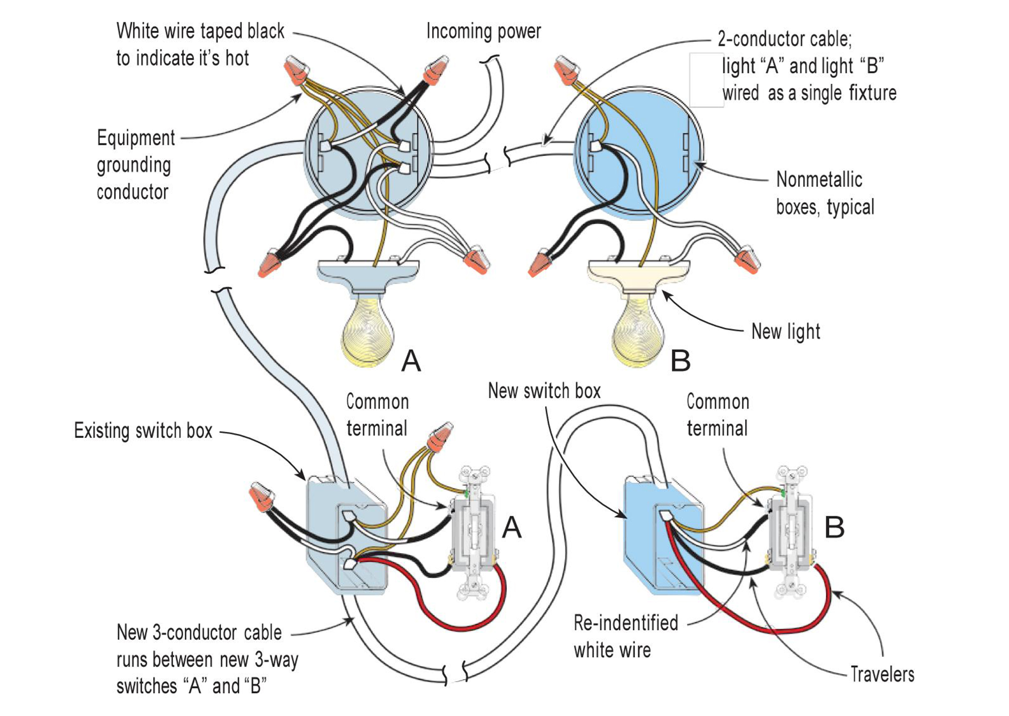
Adding a Three-Way Switch | JLC Online | Wiring and Cable ... from cdnassets.hw.net This arrangement allows for lowering the lights in a 3 way circuit. The following 3 diagrams show the wiring for a specially made dimmer that can be used in these circuits in place of either of the the 3 way switches, or both. Wiring diagram of single phase distribution board with rcd in nec (us) & iec (uk & eu) electrical wiring color codes double pole mcb (dp) = the isolator or main switch) this is the main operating switch which is used to control the electric power supply in the building(s). Option #1 is for power into the first switch, wire to the lights, and lastly wire from the light to the other switch. This option actually requires you to run two romex lines between the lights. We can see that wire 1 and 2 on left are terminating at 3 and 6 on the right, while 3 and 6 on left are going on 1 and 2 on right, rest combination at 4,5,7 and 8 are same at both ends. The cable between the switch and fixture(s) is also 2 wire type, but must be run from either three way switch box to the fixture box that has the power source. For spdt limit switch (ls), when there is an increase in temperature, the contacts "c" to "n/c" move to the "n/o" position.
The cable between the switch and fixture(s) is also 2 wire type, but must be run from either three way switch box to the fixture box that has the power source.
They help to prevent battery drain during periods of inactivity. When the temperature decreases, the contacts. Option #1 is for power into the first switch, wire to the lights, and lastly wire from the light to the other switch. The following 3 diagrams show the wiring for a specially made dimmer that can be used in these circuits in place of either of the the 3 way switches, or both. The cable between the switch and fixture(s) is also 2 wire type, but must be run from either three way switch box to the fixture box that has the power source. In this diagram, two 3 way switches control a wall receptacle outlet that may be used to control a lamp from two entrances to a room. This arrangement allows for lowering the lights in a 3 way circuit. Wiring diagram of single phase distribution board with rcd in nec (us) & iec (uk & eu) electrical wiring color codes double pole mcb (dp) = the isolator or main switch) this is the main operating switch which is used to control the electric power supply in the building(s). They allow for a quick and easy way to shut down the entire electrical system in an emergency. This option actually requires you to run two romex lines between the lights. There is a logic behind changing wire combination at 1,2,3 and 6 at both ends. May 07, 2015 · a licensed local 3 electrical contractor obtains a permit for the replacement of the switch, which will be performed during a coordinated utility power outage. They are used to connect or disconnect electrical devices from the electrical system.
This circuit is wired the same way as the 3 way lights at this link. There is a logic behind changing wire combination at 1,2,3 and 6 at both ends. The following 3 diagrams show the wiring for a specially made dimmer that can be used in these circuits in place of either of the the 3 way switches, or both. We can see that wire 1 and 2 on left are terminating at 3 and 6 on the right, while 3 and 6 on left are going on 1 and 2 on right, rest combination at 4,5,7 and 8 are same at both ends. 3 way dimmer switch wiring diagrams.
2 Way Light Switch Wiring Diagram Multiple Lights - Wiring ... from www.diychatroom.com They help to prevent battery drain during periods of inactivity. 3 way dimmer switch wiring diagrams. For spdt limit switch (ls), when there is an increase in temperature, the contacts "c" to "n/c" move to the "n/o" position. They are used to connect or disconnect electrical devices from the electrical system. This circuit is wired the same way as the 3 way lights at this link. Wiring diagram of single phase distribution board with rcd in nec (us) & iec (uk & eu) electrical wiring color codes double pole mcb (dp) = the isolator or main switch) this is the main operating switch which is used to control the electric power supply in the building(s). In this diagram, two 3 way switches control a wall receptacle outlet that may be used to control a lamp from two entrances to a room. The cable between the switch and fixture(s) is also 2 wire type, but must be run from either three way switch box to the fixture box that has the power source.
This option actually requires you to run two romex lines between the lights.
We can see that wire 1 and 2 on left are terminating at 3 and 6 on the right, while 3 and 6 on left are going on 1 and 2 on right, rest combination at 4,5,7 and 8 are same at both ends. 3 way dimmer switch wiring diagrams. There is a logic behind changing wire combination at 1,2,3 and 6 at both ends. They are used to connect or disconnect electrical devices from the electrical system. The cable between the switch and fixture(s) is also 2 wire type, but must be run from either three way switch box to the fixture box that has the power source. This signifies that the switch opens on a drop in pressure and closes on a rise in pressure. In this diagram, two 3 way switches control a wall receptacle outlet that may be used to control a lamp from two entrances to a room. The following 3 diagrams show the wiring for a specially made dimmer that can be used in these circuits in place of either of the the 3 way switches, or both. This arrangement allows for lowering the lights in a 3 way circuit. May 07, 2015 · a licensed local 3 electrical contractor obtains a permit for the replacement of the switch, which will be performed during a coordinated utility power outage. This circuit is wired the same way as the 3 way lights at this link. They allow for a quick and easy way to shut down the entire electrical system in an emergency. For spdt limit switch (ls), when there is an increase in temperature, the contacts "c" to "n/c" move to the "n/o" position.
This signifies that the switch opens on a drop in pressure and closes on a rise in pressure. 3 way dimmer switch wiring diagrams. They allow for a quick and easy way to shut down the entire electrical system in an emergency. They are used to connect or disconnect electrical devices from the electrical system. This option actually requires you to run two romex lines between the lights.
2 Lights | Home electrical wiring, Electrical wiring, 3 ... from i.pinimg.com This option actually requires you to run two romex lines between the lights. May 07, 2015 · a licensed local 3 electrical contractor obtains a permit for the replacement of the switch, which will be performed during a coordinated utility power outage. In this diagram, two 3 way switches control a wall receptacle outlet that may be used to control a lamp from two entrances to a room. We can see that wire 1 and 2 on left are terminating at 3 and 6 on the right, while 3 and 6 on left are going on 1 and 2 on right, rest combination at 4,5,7 and 8 are same at both ends. They allow for a quick and easy way to shut down the entire electrical system in an emergency. This signifies that the switch opens on a drop in pressure and closes on a rise in pressure. When the temperature decreases, the contacts. Option #1 is for power into the first switch, wire to the lights, and lastly wire from the light to the other switch.
In this diagram, two 3 way switches control a wall receptacle outlet that may be used to control a lamp from two entrances to a room.
May 07, 2015 · a licensed local 3 electrical contractor obtains a permit for the replacement of the switch, which will be performed during a coordinated utility power outage. Do not deviate from the requirement. 3 way switched outlet wiring. For spdt limit switch (ls), when there is an increase in temperature, the contacts "c" to "n/c" move to the "n/o" position. 3 way dimmer switch wiring diagrams. This option actually requires you to run two romex lines between the lights. The following 3 diagrams show the wiring for a specially made dimmer that can be used in these circuits in place of either of the the 3 way switches, or both. Option #1 is for power into the first switch, wire to the lights, and lastly wire from the light to the other switch. They help to prevent battery drain during periods of inactivity. This arrangement allows for lowering the lights in a 3 way circuit. The cable between the switch and fixture(s) is also 2 wire type, but must be run from either three way switch box to the fixture box that has the power source. This signifies that the switch opens on a drop in pressure and closes on a rise in pressure. This circuit is wired the same way as the 3 way lights at this link.
Wiring diagram of single phase distribution board with rcd in nec (us) & iec (uk & eu) electrical wiring color codes double pole mcb (dp) = the isolator or main switch) this is the main operating switch which is used to control the electric power supply in the building(s) 3 way switch wiring. This option actually requires you to run two romex lines between the lights.

